Your One-Stop Wire Mesh Fence Supplier | POLYMETAL
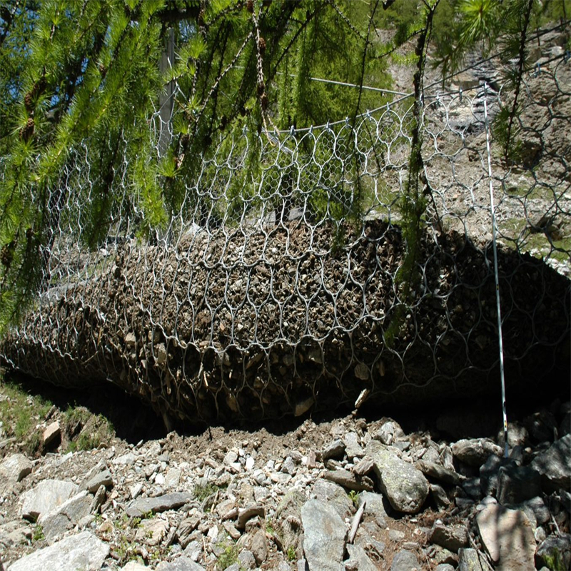


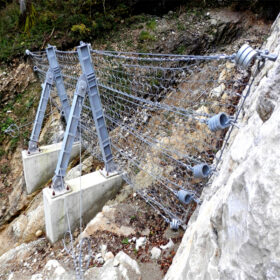
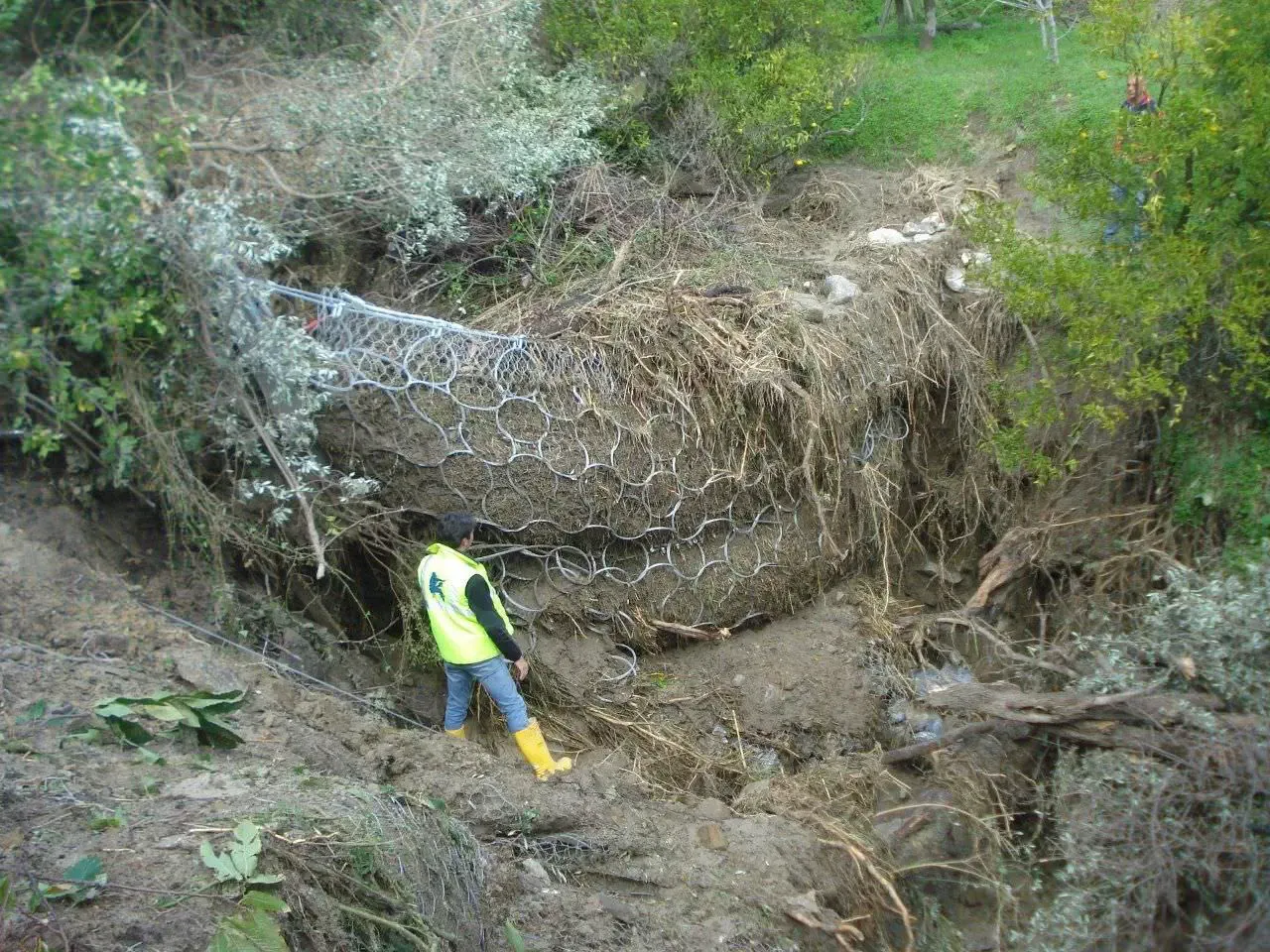
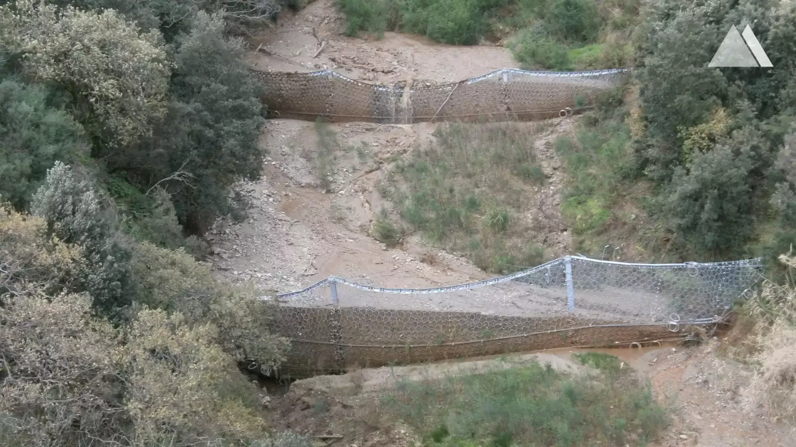
A debris flow is a fast, dangerous mixture of water, soil, rock, and wood rushing down steep channels. It can destroy roads, bridges, houses, and utilities in a few minutes.A debris flow barriers is a structure placed in a gully or torrent channel to intercept that moving mass before it reaches people and infrastructure. Modern systems are usually flexible steel-net barriers:
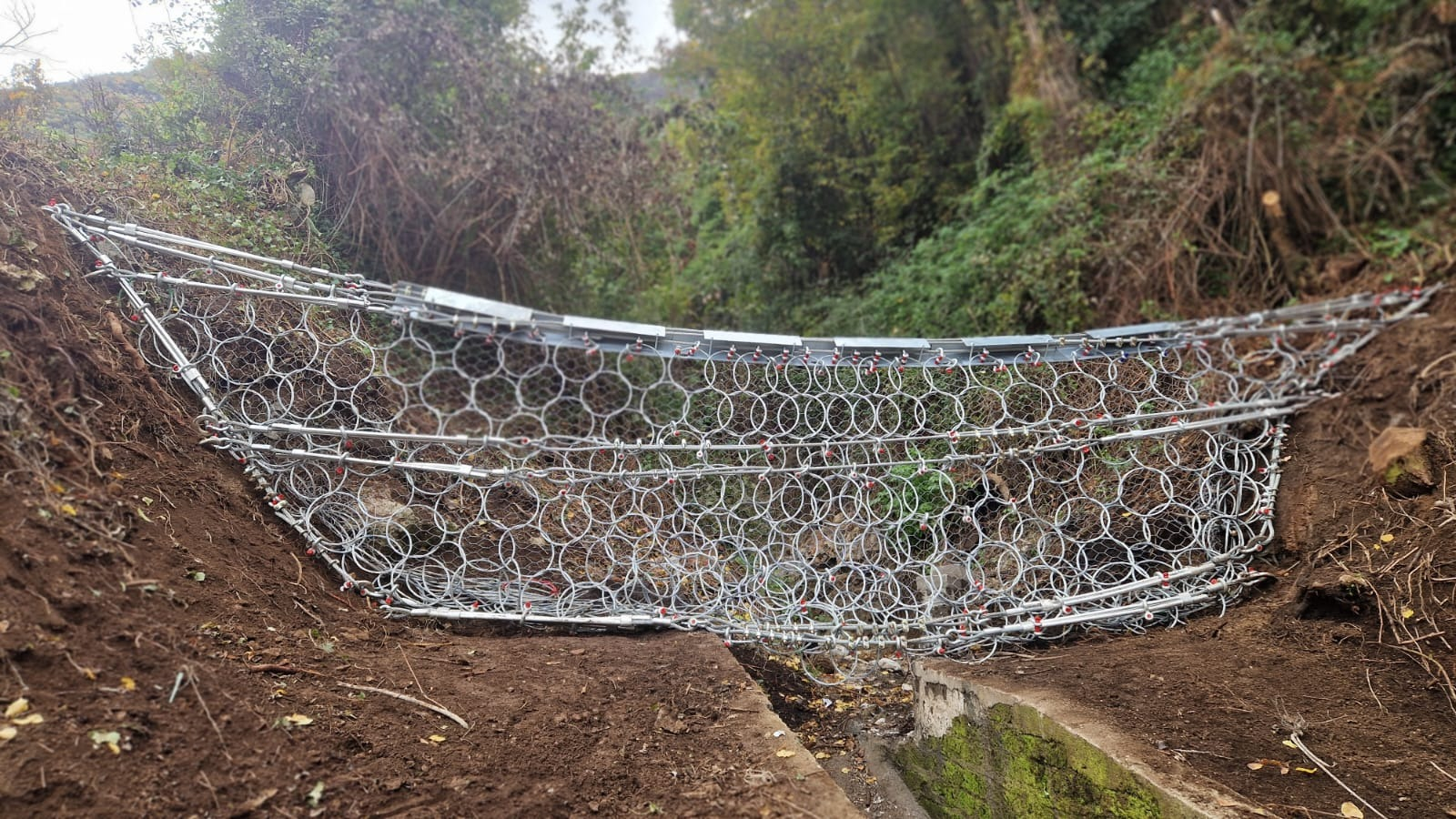
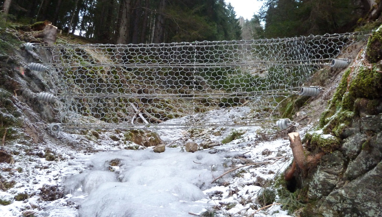
- They use high-tensile steel ring nets and wire ropes stretched between the two sides of the channel.
- They are designed for dynamic pressures of roughly 60–180 kN/m², depending on system class.
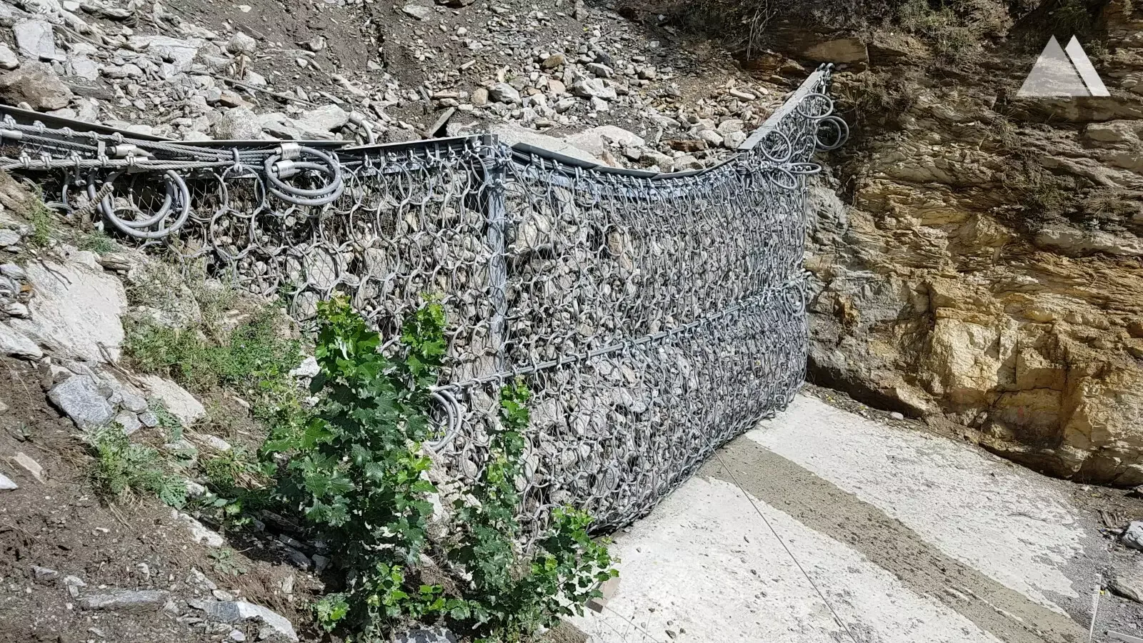
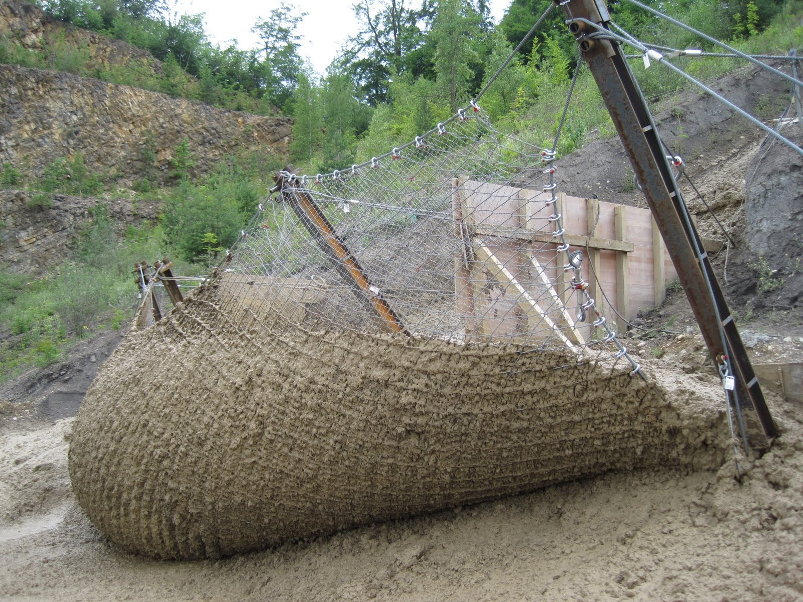
- They let water and fine sediment pass while trapping boulders, logs and coarse material.
This combination makes them a lightweight but strong protection measure in steep, hard-to-access terrain.

2. Relevant Standards and Guidelines
There is no single worldwide “one code” for debris-flow barriers, but there are well-established guidelines and product standards:
Hong Kong – GEO guidance
Discussion notes such as GEO DN 1/2012 (“Suggestions on Design Approaches for Flexible Debris-Resisting Barriers”) give methods for estimating debris-flow impact, choosing barrier class, and checking ropes, posts, and anchors.
Additional technical guidance notes cover empirical design and force-based approaches for flexible barriers.
European practice and CE-marked systems
Several manufacturers provide CE-certified barrier systems tested at full scale (impact tests, dynamic loading). Practical design guidance is given in engineering manuals and “practical guides” for debris-flow protection nets.
These documents define system classes, installation limits, test procedures, and quality control.
Project-level design documents
Research and design literature explains how to translate debris-flow characteristics into design loads and how to arrange multiple barriers in a channel.
For most projects, engineers follow local guidelines, then select a tested barrier system whose classification (height, pressure, span, energy) matches or exceeds the design requirements.

3. Data and Technical Information Debris Flow Barriers
Below is a simple data snapshot for typical flexible debris-flow barriers. Values are indicative and used for concept-level understanding.
3.1 Typical system classes debris flow barriers
| Item | Type S (Small) | Type M (Medium) | Type L (Large) |
|---|---|---|---|
| Typical use | Small channel | Medium channel | Large channel |
| Channel bottom width B | 5–7 m | 7–10 m | 10–15 m |
| Barrier height H | 4.0 m | 5.0 m | 6.0 m |
| Max span at top T | 10 m | 15 m | 20 m |
| Design debris pressure qᵈ | ≥ 60 kN/m² | ≥ 120 kN/m² | ≥ 180 kN/m² |
| Net type | Steel ring net | Steel ring net | Steel ring net |
| Ring wire diameter | 7 mm | 10 mm | 12 mm |
| Mesh opening (approx.) | 300 mm | 300 mm | 300 mm |
| Support posts | No posts | Steel posts | Heavy steel posts |
| Post spacing | – | 7–8 m | 7–8 m |
| Side anchor working load | ≥ 250 kN each | ≥ 300 kN each | ≥ 300 kN each |
| Front / crest anchors | – | 2 × 300 kN per post | 2 × 300 kN per post |
| Material | Hot-dip galvanized steel | Hot-dip galvanized steel | Hot-dip galvanized steel |
| Installation type | Single barrier | Single / multi-level | Single / multi-level |
Term meanings
| Term | Meaning |
|---|---|
| B | Channel bottom width (m) |
| H | Barrier height (m) |
| T | Max span at top (m) |
| qᵈ | Design debris pressure (kN/m²) |
Here’s a clean English table (no links, no extra text) for one example system:
Debris Flow Barrier, height 6.0 m, design debris pressure 180 kN/m², max top span 24 m.
3.2 Debris Flow Barriers Typical component data (flexible ring-net system)
| No. | Component | Item | Specification |
|---|---|---|---|
| 1 | Intercepting net | Net type | High-tensile steel ring net, ROCCO 16/3/300 or equivalent |
| Ring diameter | 300 mm | ||
| Wire diameter | 3.0 mm (high-tensile steel wire) | ||
| Wire tensile strength | ≥ 1,770 MPa | ||
| Mesh opening | approx. 300 × 300 mm | ||
| Corrosion protection | Zn–Al alloy coating, coating mass ≥ 150 g/m², hot-dip galvanized or equivalent | ||
| 2 | Support rope / cable system | Rope type | Steel wire rope 6×36 WS + IWRC, galvanized |
| Rope diameter | 22 mm (for upper, lower, boundary and diagonal ropes) | ||
| Rope wire strength | 1,770 MPa | ||
| Minimum breaking force | ≥ 284 kN per rope | ||
| Horizontal rope spacing | 1.8–2.0 m | ||
| System height | 6.0 m (net height) | ||
| 3 | Debris Flow Barriers Steel posts | Section type | Rolled H-section steel, HEB 260 (or equivalent) |
| Steel grade | S355 or higher, yield strength ≥ 355 MPa | ||
| Post height above foundation | 6.0 m (top rope guide at approx. 6.0 m) | ||
| Post spacing | 6.0–8.0 m (for max top span up to 24 m) | ||
| Base plate | Hinged base plate, thickness ≥ 25–30 mm, anchor bolt holes as required | ||
| 4 | Anchoring system | Anchor type | Steel rope anchors or self-drilling anchors with flexible anchor heads |
| Anchor rope diameter | 22.5 mm | ||
| Working load – compression anchors | 300 kN per anchor (characteristic working load) | ||
| Working load – tension anchors | 2 × 300 kN per post (characteristic working load) | ||
| Ultimate tensile capacity | approx. 470 kN per 22.5 mm anchor rope (typical) | ||
| Anchor inclination | 10–25° to ground surface, along rope force direction | ||
| 5 | Accessories & energy dissipators | Brake ring type | Steel brake ring, GS-8002 or equivalent |
| Start force (activation force) | approx. 40 kN per ring | ||
| Working force | approx. 50 kN per ring | ||
| Max plastic elongation | approx. 1.1 m per ring | ||
| Brake rings per main support rope | 4 rings per rope (typical layout for this class) | ||
| Connectors & clamps | Shackles, clamps, and fittings with WLL ≥ 1.3 × design rope force |

4. Applications
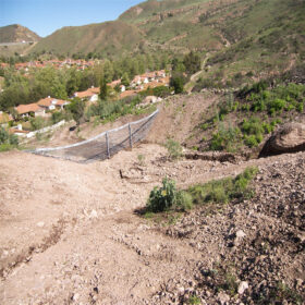
Debris flow barriers are used wherever debris flows or debris floods can threaten people or assets, for example:
Mountain torrents and gullies above villages and towns.
Roads and railways crossing steep valleys or below unstable slopes.
Bridges, culverts and tunnels where blockage by debris could cause major damage.
Hydropower and water-supply intakes that must stay clear of boulders and logs.
Post-wildfire catchments, where intense rain can trigger new debris flows for several years.
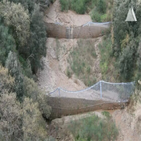
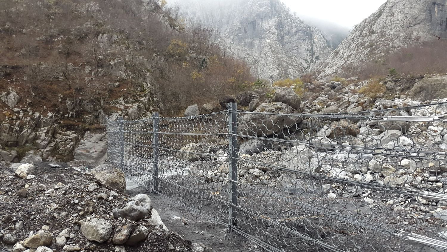
They can be installed as:
Single barriers near the element at risk (e.g. just upstream of a road or settlement).
Multiple barriers in series up the channel, so the upstream ones slow the flow and trap large blocks, and downstream ones handle the remaining debris.


5. Benefits
Key benefits of flexible debris flow barriers compared with purely rigid measures (like large concrete dams) include:
High protection efficiency
Able to retain large debris volumes, including big boulders and logs, while reducing peak flow energy.
Dynamic performance
Flexible nets and brake rings deform and absorb energy, reducing peak forces on anchors and posts and improving safety under impact.
Cost and constructability
Systems are lightweight and modular, often installed with helicopters or small equipment, giving a cost advantage in steep, remote terrain.
Lower environmental impact
Smaller foundations and open nets mean less excavation and less visual impact than massive dams; natural drainage is partly maintained.
Protection of infrastructure and people
They shield roads, bridges, railways, utilities, and settlements, reducing damage, downtime, and risk to life.
Adaptability and upgrade options
Systems can be extended or reinforced later (e.g. adding extra barriers upstream, upgrading anchors and ropes) as hazard understanding or risk tolerance changes.

6. Conclusion
Debris-flow barriers are now a standard measure in modern natural-hazard mitigation. Flexible steel-net systems, designed in accordance with current guidelines and verified through full-scale testing and certified products, can safely withstand dynamic pressures of about 60–180 kN/m² and large impact energies, while remaining relatively lightweight and easy to install; components such as the reinforced Mike pad further enhance the stability and durability of the barrier system.
When used in suitable locations, debris-flow barriers protect infrastructure and communities, offer a good cost–benefit performance, and can be combined with other measures—such as check dams, diversion channels, and land-use planning—to create a layered and resilient defence against debris-flow hazards.