 Your One-Stop Wire Mesh Fence Supplier | POLYMETAL
EMI/RFI shielding complete guides 2025 read
EMI (Electromagnetic Interference) is unwanted energy that disturbs electronics. RFI (Radio-Frequency Interference) is the RF portion of EMI (roughly kHz–GHz). EMI/RFI shielding uses conductive and/or magnetic materials plus good mechanical design to block interference from entering sensitive circuits and keep your device’s emissions from leaking out. Effectiveness is expressed as shielding effectiveness (SE) in decibels.
1) Core definitions (clear and simple)
EMI: Any electromagnetic noise that degrades performance (glitches, dropouts, resets).
RFI: EMI in the radio-frequency bands (wireless, radar, high-speed digital harmonics).
EMC (Electromagnetic Compatibility): Your device neither disturbs others nor is easily disturbed.
Shielding: Physical measures (enclosures, gaskets, mesh, coatings) that reduce radiated coupling. (For conducted paths, you use filters and proper grounding; both are needed.)
2) How interference gets in (and out)
Conducted paths: Along power/signal/ground cables and through I/O penetrations.
Radiated paths: Through air, coupling via apertures, seams, and windows.
Near-field vs. far-field: Very close sources behave like mostly electric or mostly magnetic fields; far away they behave like plane waves. The remedy (material choice, thickness) depends on which regime you’re in.
3) How shielding works (the physics you actually need)
Shielding reduces fields by a combination of:
Reflection (R) – high-conductivity surfaces reflect incident fields
Absorption (A) – energy is dissipated inside the shield (ohmic and magnetic losses)
Multiple reflections (B) – further attenuation inside layered or porous structures
A common engineering model is:
SE (dB) ≈ R + A + B, where higher is better
For fields: SE = 20·log₁₀(E_in / E_out) (or H_in / H_out)
For power: SE = 10·log₁₀(P_in / P_out)
Skin depth (how deep fields penetrate a conductor):
δ=2ωμσ\delta=\sqrt{\frac{2}{\omega \mu \sigma}}
Higher frequency (ω), higher permeability (μ), and higher conductivity (σ) reduce penetration, which is why thin copper can work well at GHz, but low-frequency magnetic fields often require high-μ alloys.
4) Materials at a glance (what to use when)
| Material class | Strengths | Typical uses | Notes |
|---|---|---|---|
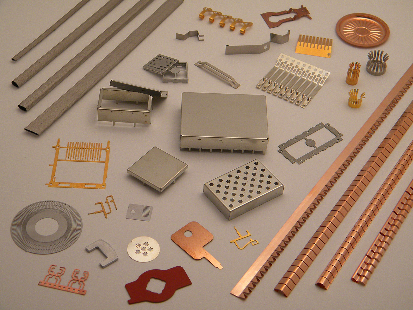
| Copper / Brass | Very high conductivity → strong reflection; easy to form | Gaskets, mesh screens, windows, small enclosures | Brass is non-sparking and forms well; copper solders easily |
| Aluminum | Light, conductive, economical | Enclosures, chassis | Oxide layer needs proper bonding/finish for low impedance joints |
| Steel / Tin-plated steel | Strong, good cost, decent conductivity; some magnetic loss | Cabinets, doors, structural panels | Often combined with conductive gaskets |
| Stainless steel | Strength + corrosion resistance | Harsh environments, mesh | Lower conductivity than Cu/Al; design joints carefully |
| High-μ alloys (e.g., mu-metal) | Excellent for low-frequency magnetic shielding | Transformers, sensors, MRI rooms | Sensitive to mechanical stress; may need anneal |
| Conductive coatings & fabrics | Lightweight, conformal | Plastic housings, seams, gaskets | Nickel/copper paints, silver-filled elastomers, conductive foam |
Rule of thumb: For electric fields and RF (tens of MHz to GHz), good conductors excel. For low-frequency magnetic fields (Hz–kHz), you need high-permeability materials and careful geometry.
5) Openings, seams, and the famous aperture rule EMI/RFI Shielding
A great shield with a bad seam is a bad shield. Control:
Aperture size vs. wavelength: keep the largest dimension ≤ λ/20 for solid performance (aim for ≤ λ/50 for high performance).
Examples:1 GHz → λ≈30 cm → max aperture ≈ 15 mm
2.4 GHz → λ≈12.5 cm → 6 mm
5 GHz → λ≈6 cm → 3 mm
Continuous, low-impedance bonds: bare-metal contact, conductive gaskets (fingerstock, conductive foam, fabric-over-foam), compression hardware to maintain pressure.
360° shield termination: avoid “pigtail” ground leads on shielded cables; use clamps or backshells for circumferential contact.
6) Vents, windows, and “air that doesn’t leak RF”
Honeycomb waveguide vents: Air passes, RF doesn’t (waveguide-below-cutoff). Higher length-to-cell-size (L/D) improves attenuation; typical L/D ≥ 3–5 for good SE.
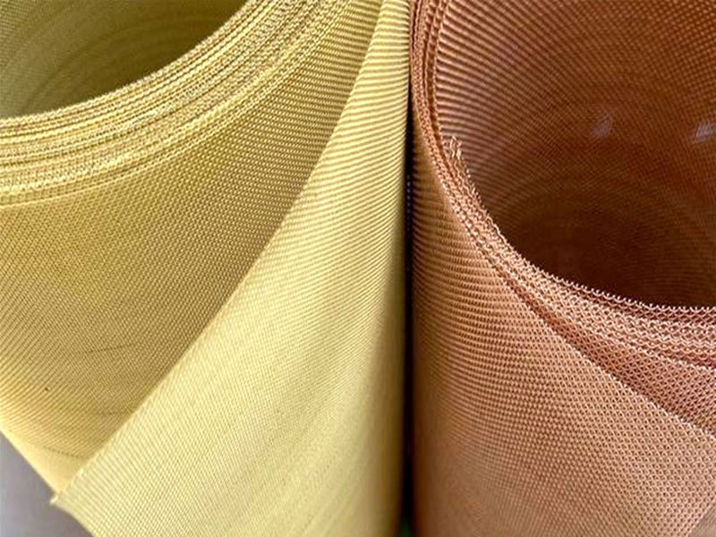
Metal mesh windows: Copper/brass/stainless mesh laminated to glass/polycarbonate. Finer mesh → better SE, but less light transmission.
Transparent conductive coatings: ITO or metal grids on glass; often combined with mesh around the perimeter.
7) Penetrations and cables (biggest “hidden” failure point)
Filtered feedthroughs for DC/power and low-frequency lines (feedthrough capacitors, EMI filters).
Shielded cables with 360° termination at the enclosure wall.
Ferrites and common-mode chokes where filtering is more practical than shielding.
8) Measuring success EMI/RFI Shielding
IEEE Std 299 – shielding effectiveness of enclosures/rooms/cabinets
MIL-STD-285 – historical method still referenced in industry
ASTM D4935 – planar materials (gaskets, fabrics, coatings) SE measurement
IEC 61000-5-7 – cabinet/large metallic structures EMC considerations
Report what matters: Frequency range, test setup, and SE curves (dB vs frequency). “60 dB @ 2 GHz” means the internal field is 1/1000 of the incident field at that frequency.
9) Fast design workflow (practical steps)
Define the threat: frequencies, field types (E/H/plane wave), field strengths, targets (e.g., SE ≥ 60 dB from 30 MHz–6 GHz).
Choose the enclosure: metal choice and thickness based on strength, environment, and frequency.
Control openings: obey λ/20 (ideally λ/50). Use honeycomb vents or multi-layer mesh for airflow.
Seal seams: conductive gaskets or fingerstock; verify contact resistance and clamping force.
Treat penetrations: filtered feedthroughs, shielded cables with 360° terminations.
Prototype & verify: materials to ASTM D4935, assemblies to IEEE 299; iterate.
10) Common mistakes (and how to avoid them)
Great material, poor joints → fix with conductive gaskets and robust mechanical clamping.
Random vent holes → size to wavelength; use honeycomb or fine mesh.
Treating low-frequency magnetic issues with thin copper → use high-μ shields or redesign geometry.
Long “pigtail” grounds on cable shields → use proper backshells/clamps for 360° bonds.
Paint between mating flanges → remove coatings where contact is required; use chromate/chemical film + conductive finish if corrosion is a concern.
11) Quick sizing examples EMI/RFI Shielding
Wi-Fi 2.4 GHz electronics bay: target SE ≥ 50–60 dB. Max opening ≈ 6 mm. Honeycomb L/D ≥ 3–5.
Multi-radio product (sub-GHz + 2.4/5 GHz): partition the PCB with shield cans over RF front ends; isolate noisy DC/DC converters with local cans and stitching vias.
Low-frequency magnetics near sensors (50/60 Hz, kHz): add mu-metal shields or increase separation; copper alone is ineffective here.
12) FAQs: EMI/RFI Shielding
What is EMI and RFI?
EMI (Electromagnetic Interference) is unwanted electromagnetic energy that disturbs electronics. RFI (Radio-Frequency Interference) is the RF subset of EMI (roughly kHz–GHz).
What does “EMI/RFI shielding” mean?
Using conductive and/or magnetic materials—plus proper joints, gaskets, and grounding—to block external interference from entering a device and to prevent your device’s emissions from leaking out.
How is performance measured?
By shielding effectiveness (SE) in decibels:
SE (dB) = 20·log10(E_in/E_out) for fields or 10·log10(P_in/P_out) for power. Higher dB = more attenuation.
How does EMI/RFI Shielding work physically?
Three mechanisms: reflection at conductive surfaces, absorption inside the material (ohmic/magnetic losses), and multiple reflections within layers or porous structures.
What’s the rule for holes and slots?
Keep the largest aperture ≤ wavelength/20 (good) and preferably ≤ wavelength/50 (better) at your highest critical frequency.
Examples: 1 GHz (λ≈30 cm) → ≤15 mm; 2.4 GHz (λ≈12.5 cm) → ≤6 mm; 5 GHz (λ≈6 cm) → ≤3 mm.
Do meshes and perforated panels actually shield?
Yes—if the opening size meets the aperture rule and the mesh is well bonded to the enclosure to provide a continuous, low-impedance path.
How do honeycomb vents allow airflow but block RF?
They act like waveguides below cutoff. Long, small cells attenuate RF while letting air pass. A higher length-to-cell-size (L/D) ratio yields better SE.
Which materials should I use?
Copper/Brass/Aluminum: high conductivity → excellent for electric/RF fields (MHz–GHz).
Stainless steel: strong and corrosion-resistant; lower conductivity, design joints carefully.
High-permeability alloys (e.g., mu-metal): best for low-frequency magnetic fields (Hz–kHz).
Conductive coatings/fabrics/elastomers: great for seams and plastic housings.
What’s the difference between near-field and far-field problems?
Near-field (very close to the source) behaves mostly electric or mostly magnetic; material choice/thickness differs (high-μ for magnetic). Far-field behaves like plane waves; good conductors excel.
How important is grounding and bonding?
Critical. EMI/RFI Shielding must have continuous, low-impedance bonds across doors, lids, and seams. Use conductive gaskets, fingerstock, or fabric-over-foam with proper compression.
How should I treat cables and penetrations?
Use shielded cables with 360° terminations at the enclosure wall and filtered feedthroughs for power/low-frequency lines. These are common failure points.
What are common gasket options?
Conductive elastomers (silver/copper-filled silicone), fabric-over-foam, beryllium copper fingerstock, and knitted wire. Choose by compression set, environmental sealing, and required SE.
What about windows and displays?
Options include metal mesh laminated to glass/polycarbonate and transparent conductive coatings (e.g., ITO). Finer grids improve SE but reduce optical transmission.
How thick does metal need to be?
At RF, once thickness exceeds a few skin depths, added thickness brings diminishing returns. For low-frequency magnetic fields, thickness and high permeability matter more.
What standards are used to test shielding?
IEEE 299 for enclosures/rooms/cabinets
ASTM D4935 for planar materials (gaskets, fabrics, coatings)
IEC 61000-5-7 guidance for cabinets/structures
Many programs also reference MIL-STD-461 for emissions/immunity limits (shielding helps you pass).
What SE values are typical targets?
Consumer/IT enclosures: 40–60 dB in the key bands
Industrial/medical: 60–80 dB
Critical/defense: 80–100 dB+ (band-dependent)
What mistakes sink a good design?
Oversized apertures, painted/oxidized mating flanges (no metal-to-metal contact), long “pigtail” cable grounds instead of 360° terminations, and untreated vents.
What’s a practical design workflow?
Define frequencies and target SE.
Pick enclosure material and thickness.
Control apertures (apply the λ/20 rule).
Seal seams with conductive gaskets; ensure clean bonding surfaces.
Treat vents (honeycomb/mesh) and cables (filters/360° terminations).
Prototype and test; iterate as needed.
Can I retrofit shielding to an existing product?
Often yes: add conductive gaskets, improve bonding, replace random holes with honeycomb vents, switch to shielded connectors/cables, and apply conductive coatings on plastic parts.
How do I specify shielding in a statement of work?
State SE (dB) vs frequency, aperture limits, gasket type/compression, vent/window SE, cable termination method, and test method (e.g., “Enclosure SE ≥ 60 dB from 1–3 GHz per IEEE 299”).
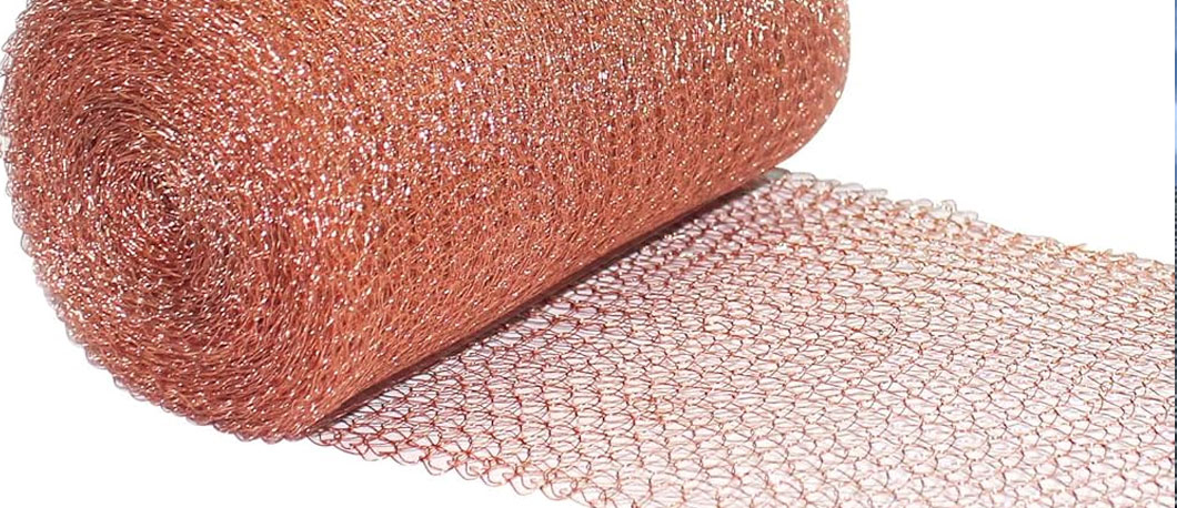
Where do mesh materials like brass or copper screens fit in?
They’re ideal for vent/opening shielding: conductive, formable, and available in many mesh counts. Ensure the mesh opening and frame bonding meet your frequency and SE targets.
EMI/RFI shielding is not just “put metal around it.” It’s conductive paths that stay continuous, apertures sized to wavelength, proper treatment of vents and cables, and verification against a standard. Do those four things well—and pick the right material for the frequency regime—and you’ll hit both regulatory compliance and real-world reliability with confidence.
Conclusion (updated with copper wire mesh)
EMI/RFI shielding isn’t just “put metal around it”—it’s a disciplined blend of the right materials, tight mechanical design, and objective verification. Use good conductors for RF (MHz–GHz) and high-permeability alloys for low-frequency magnetic fields; enforce the λ/20 aperture rule (ideally λ/50), maintain clean metal-to-metal seams with conductive gaskets, and terminate shielded cables 360° at the enclosure wall. Validate performance as shielding effectiveness (SE) in dB across the bands that matter.
Within that toolkit, copper wire mesh is a naturally effective choice for vents, windows, and localized openings: it offers very high conductivity for strong reflection, easy forming and solderability for robust bonding, and fine, controllable apertures to meet wavelength-based limits. Use copper mesh where you need airflow or visibility without RF leakage—laminate it to glass/polycarbonate for display windows, frame it tightly to create a continuous low-impedance path, and pick the mesh count so the largest opening stays below your highest-frequency requirement. In harsher environments, you can switch to tinned/treated copper or alternative alloys, but for many electronics enclosures, copper wire mesh delivers a simple, reliable, and cost-effective route to compliance.